


How to Choose a Roller Chain for Specific Machinery?
 May 11, 2026|
 View:3196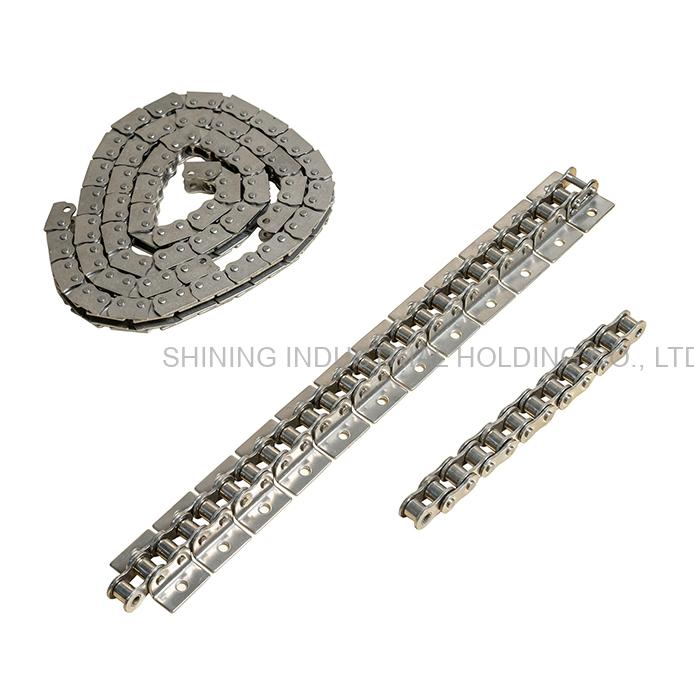
Selecting the wrong roller chain for your specific machinery is a costly mistake—one that leads to premature wear, unexpected production halts, and repeated replacement expenses. The right choice, however, keeps your equipment running efficiently for years with minimal intervention.
Whether you're building a new machine, replacing a worn chain, or upgrading an existing drive system, this guide provides a complete, practical framework for choosing a roller chain. You’ll learn what data to collect, how to perform basic calculations, which materials suit different environments, and how to avoid common pitfalls—without wading through overly technical jargon.
Key Takeaways
| Topic | Key Insight |
|---|---|
| Why correct selection matters | A poorly chosen chain fails early, causing downtime and damaging sprockets. |
| Essential data to collect | Power (kW/HP), speeds, center distance, load type, environment, duty cycle. |
| Two selection methods | Power-based (for drives) and load-based (for slow conveyors and low-speed applications). |
| Service factor | Adjusts for load shocks—smooth loads Ks ≈ 1.0, heavy shock Ks ≈ 1.5 or higher. |
| Chain pitch | The most critical dimension for matching chain to sprocket. |
| Multiple strands | Duplex/triplex chains multiply power capacity, but require proper alignment. |
| Environment | Temperature, moisture, dust, and chemicals demand specific materials and coatings. |
| When to replace | Replace a roller chain when wear elongation reaches about 1.5% for power transmission and about 2–3% for conveyors. |
| Installation basics | Align sprockets within 0.050″/ft; maintain about 1/120 of center distance in slack. |
Chapter 1: Why Choosing a Roller Chain Is a Critical Engineering Decision
A roller chain may look like a straightforward component, but the consequences of choosing incorrectly ripple through your entire operation.
The most common failure mode is wear elongation—often called "chain stretch," though the chain does not actually stretch. As pins and bushings gradually wear, the clearances increase, making the chain longer. When you select a chain without considering operating conditions, you also risk:
Catastrophic breakage when tensile strength is exceeded
Accelerated sprocket wear from mismatched pitch or poor alignment
Noise, vibration, and power loss from improper tension or wrap angle
Corrosion-related failure in wet or chemical environments
The selection process balances multiple factors: load capacity, speed, environmental conditions, maintenance access, and budget. This guide walks you through each factor in logical sequence.
Chapter 2: Information You Must Collect Before Choosing a Roller Chain
Before you open any catalog or consult a manufacturer, complete this checklist. The data you gather here determines every subsequent decision.
| Parameter | What to Record | Why It Matters |
|---|---|---|
| Power source | Motor type and rating (kW / HP) | Determines base power input |
| Driver speed | RPM of input shaft | Used with power to find chain size from rating charts |
| Desired output speed | Required RPM of driven shaft | Calculates speed ratio |
| Center distance | Distance between shaft centers (mm / inches) | Governs chain length and slack |
| Load nature | Smooth, moderate shock, heavy shock, reversing | Applies a service factor to design power |
| Duty cycle | Hours per day, starts per hour | Affects fatigue life requirements |
| Environmental conditions | Temperature, moisture, dust, chemicals | Determines material and coating needs |
| Space constraints | Available envelope for chain and sprockets | May limit sprocket size or strand count |
| Orientation | Horizontal transmission, vertical lift, inclined conveyor | Affects load calculation |
With this data in hand, you're ready to proceed to the selection methods.
Chapter 3: The Two Main Approaches to Roller Chain Selection
Method A: Power‑Based Selection (for Drive Applications)
Use this method when you know the motor or engine power. This applies to most power transmission scenarios: pumps, compressors, gearboxes, fans, and general machinery drives.
Step-by-step process:
Identify the power to be transmitted – Record the motor’s rated kW or horsepower.
Apply a service factor (Ks) – Multiply actual power by Ks to get the design power. This compensates for load fluctuations, shock, and starting frequency.
Determine small sprocket speed – Typically the faster-running shaft.
Locate tentative chain – Using a power rating table, find the chain size where design power intersects with small sprocket speed.
Select number of sprocket teeth – Minimum 17 teeth for smooth operation at moderate speeds; 21+ teeth for high-speed applications to minimize vibration.
Verify with manufacturer data – Confirm the selected chain meets or exceeds design power.
Service Factor (Ks) Guide – Choose the Correct Column
| Load Type | Example Machines | Electric Motor | Moderate Motor | High‑Shock Engine |
|---|---|---|---|---|
| Smooth (Ks = 1.0–1.2) | Belt conveyors, centrifugal pumps, textile machines | 1.0 | 1.0 | 1.2 |
| Moderate (Ks = 1.2–1.5) | Compressors, general machine tools, dryers | 1.3 | 1.2 | 1.4 |
| Heavy shock (Ks = 1.5–1.8) | Crushers, presses, construction equipment, oil‑field machinery | 1.5 | 1.5 | 1.7 |
Design Power = Actual Power × Service Factor
For multiple-strand chains, power ratings multiply. For duplex (two-strand) chains, multiply by approximately 1.7; for triplex (three-strand) chains, multiply by approximately 2.5.
Method B: Load‑Based Selection (for Conveyors and Slow‑Speed Applications)
Use this method when chain speed is low (typically below about 160 ft/min or 0.8 m/s) and the primary load comes from tension, not power.
Calculate total chain tension – Sum of: weight of chain, weight of conveyed material, friction forces, and any incline/decline components.
Apply a safety factor – For most industrial conveyors, a safety factor of between 5:1 and 8:1 (breaking strength to working load) is standard.
Select tentative chain – Choose a chain with maximum allowable load greater than calculated working tension.
Check roller load – For applications where rollers directly support heavy loads, verify the roller diameter and material can withstand surface pressures.
Finalize based on wear life – In abrasive or harsh environments, wear (not breakage) is the limiting factor.
Chapter 4: Understanding Chain Pitch and Sizes
Pitch is the most critical dimension of any roller chain: the distance between the centers of two adjacent pins. All other dimensions—roller diameter, inside width, plate thickness—scale from pitch.
| ANSI No. | Pitch (inches) | Pitch (mm) | Typical Applications |
|---|---|---|---|
| #25 | 1/4″ (0.250) | 6.35 | Light instrument drives |
| #35 | 3/8″ (0.375) | 9.525 | Small machinery, packaging |
| #40 | 1/2″ (0.500) | 12.70 | General light‑duty drives |
| #50 | 5/8″ (0.625) | 15.875 | Industrial machinery, agriculture |
| #60 | 3/4″ (0.750) | 19.05 | Mixers, medium conveyors |
| #80 | 1″ (1.000) | 25.40 | Heavy‑duty conveyors, crushers |
| #100 | 1‑1/4″ (1.250) | 31.75 | Mining equipment, steel mills |
| #120 | 1‑1/2″ (1.500) | 38.10 | Very heavy loads, extreme conditions |
How to identify an unknown chain: Use calipers to measure three dimensions: pitch, roller diameter, and the inside width between inner plates. ANSI numbering tells you the pitch in eighths of an inch—for example, #40 means 4/8″ = 1/2″ pitch.
ANSI vs. ISO: Even when pitch is identical (e.g., #40 at 1/2″ / 12.70 mm vs. ISO 08B at 12.70 mm), chains from different standards are not interchangeable. Roller diameters and inside widths differ, affecting how the chain engages with the sprocket. Always match chain and sprocket to the same standard.
Chapter 5: Single, Duplex, or Triplex – How Many Strands Do You Need?
| Configuration | Power Multiplier (Approx.) | Best When |
|---|---|---|
| Single strand (‑1) | 1.0x | Light to moderate loads, unlimited width |
| Duplex (‑2) | 1.7x | Higher power, but pitch change not feasible |
| Triplex (‑3) | 2.5x | Maximum power without increasing pitch |
The strand factor for two strands is about 1.7; for three strands, about 2.5. However, load distribution across strands is never perfectly even, so real-world power capacity is slightly less than the theoretical multiplier.
Important: Duplex chains require duplex (double-strand) sprockets. You cannot run a duplex chain on single-strand sprockets.
Chapter 6: Matching Your Environment: When Standard Chain Is Not Enough
Standard carbon steel roller chain works well in clean, dry, temperature‑controlled conditions. Outside that range, material selection becomes the dominant factor in service life.
| Operating Environment | Recommended Solution | Why This Matters |
|---|---|---|
| Wet / humid / outdoors | Zinc‑ or nickel‑plated carbon steel, or stainless steel | Prevents rust and corrosion |
| High temperature (exceeding about 250°F / 120°C) | High‑temperature alloys; expect reduced load ratings | Standard lubricants degrade; materials lose strength |
| Low temperature (below about 15°F / -9°C) | Low‑temperature alloys; special low‑temp lubricants | Cold makes steel brittle |
| Abrasive dust (cement, mining, grain) | Hardened pins and bushings; sealed lubrication systems | Dramatically extends wear life |
| Corrosive chemicals | Stainless steel (304 or 316) | Resists chemical attack |
| Food / washdown environments | Stainless steel; lubricant‑free or NSF‑rated chain | Meets hygiene and corrosion requirements |
For extremely abrasive environments, consider chains with special surface treatments. Chemically applied nickel coatings combine wear resistance with corrosion protection.
Chapter 7: Connecting Links and Offset Links – What You Must Know
| Link Type | Strength Impact | Best Practice |
|---|---|---|
| Press‑fit connecting link | Near full chain strength | Preferred for all performance‑critical drives |
| Slip‑fit connecting link | Up to 20‑30% weaker | OK for light‑duty, low‑speed applications only |
| Single‑pitch offset link | About 35% weaker | Avoid in high‑load, high‑speed, or shock‑prone applications |
| Two‑pitch offset link | Much stronger than single‑pitch | Preferred when an odd number of links is unavoidable |
Offset links (also called ½ links or crank links) are used to achieve an odd number of pitches. Whenever possible, design your center distance to use an even number of pitches, eliminating offset links entirely.
Chapter 8: Measuring Wear Elongation – When to Replace Your Chain
The term "chain stretch" is a misnomer. Chains do not actually stretch; wear at the pin‑bushing interface increases internal clearances, making the chain longer.
Replacement thresholds:
| Application Type | Maximum Wear Elongation |
|---|---|
| Power transmission drives (fewer than 60 teeth on sprocket) | About 1.5% elongation |
| Conveyor applications | About 2–3% elongation |
How to measure: Under a light tension to remove slack, measure across a known number of pitches (at least six pitches) using a steel tape or caliper.
Elongation (%) = (Measured Length – Theoretical Length) ÷ Theoretical Length × 100
If your chain hits the replacement threshold, change it immediately. Continuing to run an excessively worn chain will damage your sprockets, dramatically increasing replacement cost.
Chapter 9: Installation and Tensioning Guidelines
Even the best‑selected roller chain will underperform if installed incorrectly.
Pre‑installation checklist:
Confirm shafts are parallel and sprockets are aligned in the same plane
Alignment precision: within about 0.050″ per foot (approx. 0.25°) for most single‑strand drives
Verify sprockets have no burrs, nicks, or damaged teeth
Ensure the chain will engage with at least three sprocket teeth at all times
Tension guidelines: As a rule of thumb, the chain should deflect about 1/120th of the center distance when moderate pressure is applied to the slack strand.
Trial run: Before full‑speed operation, run the drive at slow speed to check for proper fit, adequate chain slack, sufficient lubrication, and no interference with the chain case.
Chapter 10: Choosing a Roller Chain Manufacturer – What SHINING Delivers
After you have determined the technical specifications—pitch, number of strands, material, and environmental requirements—the final step is selecting a manufacturer you can trust.
SHINING brings over 20 years of experience in precision-engineered roller chain manufacturing, with a 36,000㎡ factory and an annual production capacity exceeding 15,000 tons. The company serves more than 40 countries across industries including cement, mining, steel, automotive, construction, energy, wastewater, sugar and palm oil, lumber and wood processing, pulp and paper, and grain milling.
Why choose SHINING for your roller chain needs?
OEM expertise with global standards – SHINING roller chains are spec‑matched to top‑tier standards, delivering approximately 20% cost efficiency without compromising quality.
Quality assurance – ISO‑certified processes with full material traceability and 100% load testing on every chain produced.
Supply chain resilience – Based in the Yangtze River Delta, SHINING ensures raw material response times under 72 hours.
Cross‑industry engineering mastery – Engineers with 20+ years in mining, cement, and steel solve extreme‑condition failures.
Customized services – For non‑standard requirements, SHINING accepts customer drawings or samples, submits proposals for approval, and manufactures accordingly.
From standard ANSI/ISO roller chains to application‑specific designs, SHINING provides the reliability, technical fit, and engineering support your machinery demands.


